Title: Building a Fun and Smart Home with a DIY Smart Doorbell Introduction: In the exciting world of electronics, there's nothing quite as thrilling as creating your very own smart home gadgets. Today, we'll embark on a journey to build a Smart Doorbell using simple and easily accessible equipment like the Arduino Uno, an IR proximity sensor, and a buzzer. This DIY project is not only a fantastic introduction to electronics but also a step towards transforming your home into a tech-savvy haven. So, gear up, young inventors, as we venture into the world of smart homes! Materials You'll Need: 1. Arduino Uno: The brain of our smart doorbell, capable of processing information and controlling the connected devices. 2. IR Proximity Sensor: A nifty gadget that detects the presence of objects in its vicinity. 3. Buzzer: This component will be the voice of our smart doorbell, alerting you when someone approaches. Step 1: Setting Up the Arduino Uno: Begin by connecting your Arduin...
Amplitude modulation;
Amplitude modulation ; Before we approach the term amplitude modulation , we first need to understand what we mean by the term modulation . the term 'modulation' in electronics is simply a means of manipulating a signal.
"Modulation is (electronics) the transmission of a signal by using it to vary a carrier wave; changing the carrier's amplitude, frequency or phase". from this definition it is clear to us that a signal could be Amplitude modulated , Frequency modulated and Phase modulated.
Amplitude modulation simply means varying the amplitude of a signal ( carrier wave/signal) to carry useful information .Amplitude modulation as used in communication is the use of a low frequency audio signal to vary the amplitude of a high frequency signal(carrier signal), so that the resulting signal contains both the Audio signal and the High frequency signal.
Amplitude modulation simply means varying the amplitude of a signal ( carrier wave/signal) to carry useful information .Amplitude modulation as used in communication is the use of a low frequency audio signal to vary the amplitude of a high frequency signal(carrier signal), so that the resulting signal contains both the Audio signal and the High frequency signal.
Tip: imagine trying to throw a paper to a far distance ( it doesn't go far) , then imagine wrapping the paper on a stone then throwing it (it travels farther than without the stone).
this analogy illustrate what amplitude modulation is. it is nearly impossible to transmit a low frequency signal (due to the conditions such as antenna length and other factors) but when we wrap the signal(low frequency) around a high frequency signal(carrier ) transmission of the low frequency signal can be achieved.
this analogy illustrate what amplitude modulation is. it is nearly impossible to transmit a low frequency signal (due to the conditions such as antenna length and other factors) but when we wrap the signal(low frequency) around a high frequency signal(carrier ) transmission of the low frequency signal can be achieved.
In order to understand Amplitude modulation , we are going to consider the following blocks or stages.
1. Low frequency signal (audio signal)- Modulating signal
2.High frequency signal ( oscillator)- the carrier wave/signal
3. Modulator.
Amplitude modulation is performed in the modulator stage. the two signals enters into the modulator , the high frequency signal called the carrier wave which is created by a high frequency oscillator at the requires signal level and the low frequency(modulating ) signal coming either from a mic or some other low frequency source being amplified by a low frequency amplifier( using an op amps or transistors).
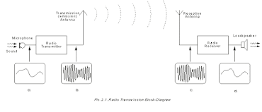
The output of the modulator is a amplitude modulated signal, this new signal contains both the carrier wave and the low frequency signal, the signal may be amplified and lead to transmission phase by an antenna ( the low frequency signal can be extracted using a demodulator(Receiver)).
The above circuit shows the Transmitting and a Receiving end of Amplitude modulation(AM). The transmitter produces a modulated signal(it consist of the carrier and modulating signal) and it is being transmitted via antenna , while the Receiver detects this signal and then demodulates it ( extract the useful information , usually a low frequency audio signal ) taking the useful information signal . the receiver also consist of a amplifier to amplifier the extracted signal , which is then fed to a speaker.
That'll be all presently , thanks for Reading and I will be writing an update on Amplitude modulation , I will also create my own AM circuit and I will be explaining how it works . Till then, STAY CREATIVE


Nice post, Elijah .
ReplyDeleteVery informative