Title: Building a Fun and Smart Home with a DIY Smart Doorbell Introduction: In the exciting world of electronics, there's nothing quite as thrilling as creating your very own smart home gadgets. Today, we'll embark on a journey to build a Smart Doorbell using simple and easily accessible equipment like the Arduino Uno, an IR proximity sensor, and a buzzer. This DIY project is not only a fantastic introduction to electronics but also a step towards transforming your home into a tech-savvy haven. So, gear up, young inventors, as we venture into the world of smart homes! Materials You'll Need: 1. Arduino Uno: The brain of our smart doorbell, capable of processing information and controlling the connected devices. 2. IR Proximity Sensor: A nifty gadget that detects the presence of objects in its vicinity. 3. Buzzer: This component will be the voice of our smart doorbell, alerting you when someone approaches. Step 1: Setting Up the Arduino Uno: Begin by connecting your Arduin...
Introduction to DC motors
A DC motor is an electric motor that converts direct current electrical energy into mechanical energy. They operate based on the principle of "Force acting on a coil of wire in a magnetic field". This principle states that when a current-carrying conductor is placed in a magnetic field, the conductor experiences a mechanical force.
The direction of this force is determined by Fleming's left-hand rule, and the magnitude of the force can be expressed as:
F= B*I*L ( in newtons)
where
F- force(newtons)
B- magnetic field (Tesla)
I- Current ( Ampere)
L- Length of the conductor.
According to Fleming's left-hand rule, the direction of the force is perpendicular to both the conductor and the magnetic field.

_80_degree_split_ring.gif)
Tip: if the direction of current flow is reversed, the direction of rotation of the motor changes also.
Controlling DC motors
DC motors find use in various applications where operating at full speed is not always necessary. Therefore, a technique is required to achieve complete control over the DC motor.There are two critical aspect to this control.
1.Speed
2. Direction.
Let's explore some basic techniques for controlling a DC motor.
Introduction to Speed Control
we can control the speed of a DC motor by simply controlling the voltage across the motor. the speed of the DC motor vary with the voltage across it. so , to achieve control and vary the speed of the motor , we first need a method of controlling the voltage across it. one of the commonest method of doing this is using a PWM signal (Pulse width Modulated).
Pulse Width Modulation
We can control the speed of a DC motor by adjusting the amount of electricity it gets. The more electricity, the faster it spins. To control this, we use a technique called Pulse Width Modulation (PWM).
PWM is a technique which allows us to vary the average value of the voltage(current) fed to a load by switching the power supply on and off at a fast rate. it's a way to make the motor run slower or faster by quickly turning the power on and off. Imagine it like a light switch that blinks so fast you can't see it. The longer the switch stays on, the brighter the light (or the faster the motor).
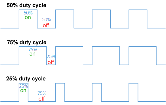
The brightness, or motor speed, depends on something called the "duty
cycle." The duty cycle is just the fraction of time the power is turned
on compared to the total time.
Duty cycle = (T(on) / T (tot) ) * 100
it is usually expressed in percentage
T(on) - it is the on time of the signal
Toff- the time the signal remains in its off state
T(tot) - the period of the signal( on time + off time).
For example, if we turn the power on for 10 milliseconds and off for 10 milliseconds in a 20-millisecond cycle, the duty cycle is 50%. This means the motor will run at half its full speed.
T(on) = 10ms;
T(off) = 10ms
T(tot) = 20ms;
Duty cycle = ( 10 / 20 ) * 100 == 50 %
average voltage = Duty cycle * supply Voltage
== 0.5 * 5 = 2.5v
A duty cycle of 50% gives us an average voltage of half the supply voltage. With an ON time of 18ms, we have a duty cycle of 90%. Hence, the average voltage is 4.5volts and the motor spins faster.
Tip: if the supply is in the ON state more ,than when it is in the OFF state , the duty cycle increases , hence the average voltage increases.
We can use the PWM signal to control the motor by connecting it to something called a transistor or a gate. By changing the duty cycle, we can make the motor spin faster or slower.
This PWM technique helps us control the motor's speed, but we still need to figure out how to make it go forward or backward; control the direction of rotation.
Introduction to Direction Control
H-BRIDGE DC motor control
The direction of rotation of a DC motor can be controlled by changing the direction of the current flow through the motor. The most common method of controlling the direction of rotation of a motor is through an H-bridge .
An H-bridge circuit contains four switching elements (Transistors(BJTs & FETs), in some high voltage applications IGBTs are used ) with a load at the center , forming a H-like configuration.
An H-bridge is like a clever switch. The four switching elements can be
turned on and off separately. By turning on two parts at a time, we can
make the motor spin one way or the other.

In an H-bridge circuit, all the switching elements can be switched ON and OFF independently. By switching two switching elements ON (whilst keeping the remaining two OFF) at a particular time, we can change the direction of rotation of motor.
The operation of an H-bridge is simple. if Q1 and Q4 are turned ON , the left lead of the motor connects to the power supply and the right lead connects to ground. Current flows through the motor and the motor begins to spin, let say forward direction( clockwise rotation)

if Q2 and Q3 are turned ON (whilst Q1 and Q4 are OFF), the reverse will happen and the motor begins to spin, in the backward direction( counter-clockwise rotation).

In an H-bridge , you should never turn ON both Q1 and Q2(or Q3 and Q4) at the same time . this will short the power supply and may destroy the bridge.
Tips: we should never turn on both Q1 and Q2 (or Q3 and Q4) at the same time. That would be like pressing the gas and the brake pedal at once, and it can damage the motor.
To get full control over a DC motor that you have ,you may need to get an Integrated Circuit (IC) dedicated for motor control that can achieve both speed and direction control. One of the recommended options is the L298N dual H-bridge motor driver.
Comments
Post a Comment