Title: Building a Fun and Smart Home with a DIY Smart Doorbell Introduction: In the exciting world of electronics, there's nothing quite as thrilling as creating your very own smart home gadgets. Today, we'll embark on a journey to build a Smart Doorbell using simple and easily accessible equipment like the Arduino Uno, an IR proximity sensor, and a buzzer. This DIY project is not only a fantastic introduction to electronics but also a step towards transforming your home into a tech-savvy haven. So, gear up, young inventors, as we venture into the world of smart homes! Materials You'll Need: 1. Arduino Uno: The brain of our smart doorbell, capable of processing information and controlling the connected devices. 2. IR Proximity Sensor: A nifty gadget that detects the presence of objects in its vicinity. 3. Buzzer: This component will be the voice of our smart doorbell, alerting you when someone approaches. Step 1: Setting Up the Arduino Uno: Begin by connecting your Arduin...

This tiny 88-108Mhz FM transmitter bug measures just 10mm x 17mm in size and as you can see in the photos the biggest components are just the microphone and the battery. You can use a small microphone from an older cell phones, they are small in size and have an excellent sensitivity. For an effective power supply the 9V battery (Duracell) is excellent and allows several hours of battery life, but if you want to have a smaller size it is better to use 2 or 3 lithium cells like the 2032 used in PCs. The circuit works well from 3 to 12V, the maximum range is obtained with 12V and a piece of 40-60cm cable as an antenna.
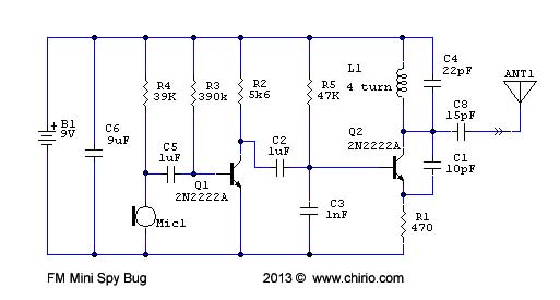
It is possible to power transmitter by small LIPO battery (3.7-4V), in that case you must change R4 to 10K and R1 to 150ohm.
The antenna length varies according to the output frequency, 300 / f then divides by 4 so as to have the antenna length in 1/4 wave length. 100Mhz = 75cm - 10% to compensate for losses make 68cm. For simplification the 2N2222A is also used as a BF amplifier, the operation is good without distortion, much depending on the quality of the microphone. The Q2 is configured as a Colpitts oscillator. The working frequency can be calibrated from 70 to 400Mhz only by changing the tuned circuit formed by L1 and C4 Always use the usual RF transistor like 2N2222A, or MMBT2222A in SMD form factor. Frequency according to the LC + antenna length 70Mhz: C4 33pF, L1 10 turns, 90cm antenna 100Mhz: C4 22pF, L1 7 turns, 68cm antenna 150Mhz: C4 15pF, L1 6 turns, 45cm antenna 430MHz: C4 4.7pF, L1 3 turns, 15cm antenna From the table you can find the indicative values for the working frequency, this applies to SMD mounting on 0.8mm pcb with reduced dimensions, with traditional assemblies the frequencies can vary a lot and also do not oscillate. Not using the Varicap Diodes to modulate the frequency, we will have a suitable output for Wide FM receivers, with the reception in FM narrow there could be some distortions, it is also possible to hear something in AM but the distortion is greater, the best quality listenable in headphones is then with a scanner receiver in WFM mode. Using a wired Tx antenna, Yagi antenna in reception and headphones, it is possible to reach 300-500 meters in open field.   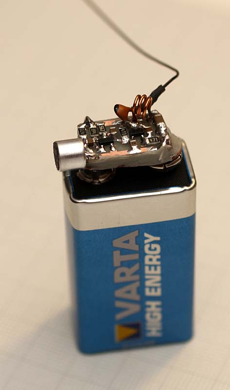 |
Comments
Post a Comment