
Building a Fun and Smart Home with a DIY Smart Doorbell

  Title: Building a Fun and Smart Home with a DIY Smart Doorbell Introduction: In the exciting world of electronics, there's nothing quite as thrilling as creating your very own smart home gadgets. Today, we'll embark on a journey to build a Smart Doorbell using simple and easily accessible equipment like the Arduino Uno, an IR proximity sensor, and a buzzer. This DIY project is not only a fantastic introduction to electronics but also a step towards transforming your home into a tech-savvy haven. So, gear up, young inventors, as we venture into the world of smart homes! Materials You'll Need: 1. Arduino Uno: The brain of our smart doorbell, capable of processing information and controlling the connected devices. 2. IR Proximity Sensor: A nifty gadget that detects the presence of objects in its vicinity. 3. Buzzer: This component will be the voice of our smart doorbell, alerting you when someone approaches. Step 1: Setting Up the Arduino Uno: Begin by connecting your Arduin...

FM antenna boost

Active FM Antenna Booster


Active FM Antenna Booster


This is a simple active antenna booster. This amplifier will pull in all distant FM stations clearly. The circuits is configured as a common-emmitter tuned RF preamplifier wired around VHF/UHF transistor Q1. Input coil L1 consists of four turns of 20SWG enamelled copper wire (slightly space wound) over 5mm diameter former. It is tapped at the first turn from ground lead side. Coil L2 is similar to L1, but has only three turns. Pin configuration of transistor 2SC2570 is shown in the fm antenna booster schematic. Adjust input/output trimmers (VC1/VC2) for maximum gain.
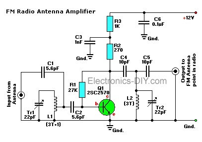
Active FM Amplifier

Parts List:
R1 = 27K
R2 = 270 ohm
R3 = 1K

Tr1,Tr2 = 22pF, trimmer cap (15-40pF)
C1,C2 = 5.6pF
C3 = 0.001uF (1nF), ceramic
C4,C5 = 0.01 (10nF), ceramic
C6 = 0.1uF (100nF), ceramic

Q1 = 2SC2498, 2SC2570, 2N5179, SK9139, or NTE10. NPN VHF/UHF transistor
L1 = 4 turns of 20SWG magnet wire, 5mm diameter. (so-called 3T+1)
L2 = 3 turns of 20SWG magnet wire, 5mm diameter.

With only a small handfull of parts you can built this trusty FM Amplifier.

This amplifier will pull in all distant FM stations clearly. The circuit is configured as a common-emitter tuned RF pre-amplifier wired around VHF/UHF transistor Q1.

All capacitors are ceramic, and 50V is the standard but the 25V types work fine too. Trimmer capacitors Tr1 and Tr2 (22pF) are adjusted for maximum gain.
Input coil L1 consists of 4 turns of 20SWG enameled copper wire over a 5mm diameter former. It is tapped at the first turn from the ground lead side. Coil L2 is similar to L1, but has only three turns. Pin configuration is shown in the diagram.


circuit credit goes to electronics diy.com

Droid Electronics 

Comments

  1. Emperor Casino: Claim Your Welcome Bonus!
    Find an ideal site for all types of games like video poker, baccarat, 제왕카지노 roulette, 카지노사이트 keno, craps, septcasino keno and more!

    ReplyDelete

Post a Comment

Popular posts from this blog

How DC motor works and control.

Introduction to DC motors A DC motor is an electric motor that converts direct current electrical energy into mechanical energy. They operate based on the principle of "Force acting on a coil of wire in a magnetic field". This principle states that when a current-carrying conductor is placed in a magnetic field, the conductor experiences a mechanical force. The direction of this force is determined by Fleming's left-hand rule, and the magnitude of the force can be expressed as:                   F= B*I*L ( in newtons) where  F- force(newtons) B- magnetic field (Tesla) I- Current ( Ampere) L- Length of the conductor. According to Fleming's left-hand rule, the direction of the force is perpendicular to both the conductor and the magnetic field.   Tip: if the direction of current flow is reversed, the direction of rotation of the motor changes also. Controlling DC motors DC motors find use in various applications where ope...

Flame Detectors Explained

 Flame sensor/ detectors: Flame detectors(sensors) detect the presence of flame.  just as every other sensor operate ; they detect a change in a physical phenomenon and then produce an output signal proportional to the change in the physical phenomenon being sensed or detected. The presence of fire which relates to flames is a physical condition to be watched against  and since this is an unwanted condition , there arise the need to constantly watch(detect) against it and eliminate it as quick as possible when detected . Flame detectors are devices that watch against flames (fire ) , it may also be called a fire detector.  A flame sensor detects a flame but what physical or measureable characteristics of a flame does it detects??. with this question in mind , we need to overview flames , identify the properties of a flame that can be detected /measured / sensed  and work on the best methodology to detect flames. OVERVIEW OF FLAMES A flame is a mixture of reac...

Astable multivibrator

Astable multivibrator Astable Multivibrators are free running oscillators which oscillate between two states continually producing two square wave output waveforms.            Introduction  Regenerative switching circuits such as  Astable Multivibrators   are the most commonly used type of relaxation oscillator because not only are they simple, reliable and ease of construction they also produce a constant square wave output waveform. Unlike the Monostable Multivibrator or the Bistable Multivibrator we looked at in the previous tutorials that require an “external” trigger pulse for their operation, the  Astable Multivibrator  has automatic built in triggering which switches it continuously between its two unstable states both set and reset. The  Astable Multivibrator  is another type of cross-coupled transistor switching circuit that has  NO  stable output states as it changes from one state to the other all ...