Title: Building a Fun and Smart Home with a DIY Smart Doorbell Introduction: In the exciting world of electronics, there's nothing quite as thrilling as creating your very own smart home gadgets. Today, we'll embark on a journey to build a Smart Doorbell using simple and easily accessible equipment like the Arduino Uno, an IR proximity sensor, and a buzzer. This DIY project is not only a fantastic introduction to electronics but also a step towards transforming your home into a tech-savvy haven. So, gear up, young inventors, as we venture into the world of smart homes! Materials You'll Need: 1. Arduino Uno: The brain of our smart doorbell, capable of processing information and controlling the connected devices. 2. IR Proximity Sensor: A nifty gadget that detects the presence of objects in its vicinity. 3. Buzzer: This component will be the voice of our smart doorbell, alerting you when someone approaches. Step 1: Setting Up the Arduino Uno: Begin by connecting your Arduin...
Fire Alarm
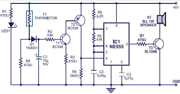
The thermistor offers a low resistance at high temperature and high resistance at low temperature. This phenomenon is employed here for sensing the fire. The IC1 (NE555) is configured as a free running oscillator at audio frequency. The transistors T1 and T2 drive IC1. The output(pin 3) of IC1 is couples to base of transistor T3(SL100), which drives the speaker to generate alarm sound. The frequency of NE555 depends on the values of resistances R5 and R6 and capacitance C2.When thermistor becomes hot, it gives a low-resistance path for the positive voltage to the base of transistor T1 through diode D1 and resistance R2. Capacitor C1 charges up to the positive supply voltage and increases the the time for which the alarm is ON.
The larger the value of C1, the larger
the positive bias applied to the base of transistor T1 (BC548). As the collector of T1 is coupled to the base of transistor T2, the transistor T2 provides a positive voltage to pin 4 (reset) of IC1 (NE555). Resistor R4 is selected s0 that NE555 keeps inactive in the absence of the positive voltage. Diode D1 stops discharging of capacitor C1 when the thermistor is in connection with the positive supply voltage cools out and provides a high resistance path. It also inhibits the forward biasing of transistor T1. This circuit can be powered from a 6V battery or a 6V power supply. The thermistor can be mounted on a heat resistant material like mica to prevent it from damage due to excessive heat. The LED acts as an indication when the power supply is switched ON.
Droid Electronics
|
Comments
Post a Comment