
Building a Fun and Smart Home with a DIY Smart Doorbell

  Title: Building a Fun and Smart Home with a DIY Smart Doorbell Introduction: In the exciting world of electronics, there's nothing quite as thrilling as creating your very own smart home gadgets. Today, we'll embark on a journey to build a Smart Doorbell using simple and easily accessible equipment like the Arduino Uno, an IR proximity sensor, and a buzzer. This DIY project is not only a fantastic introduction to electronics but also a step towards transforming your home into a tech-savvy haven. So, gear up, young inventors, as we venture into the world of smart homes! Materials You'll Need: 1. Arduino Uno: The brain of our smart doorbell, capable of processing information and controlling the connected devices. 2. IR Proximity Sensor: A nifty gadget that detects the presence of objects in its vicinity. 3. Buzzer: This component will be the voice of our smart doorbell, alerting you when someone approaches. Step 1: Setting Up the Arduino Uno: Begin by connecting your Arduin...

Resistor and their colour code

Standard Resistor Values and Color 

resistor color code are as follows


The colors brown, red, green, blue, and violet are used as tolerance codes on 5-band resistors only. All 5-band resistors use a colored tolerance band. The blank (20%) “band” is only used with the “4-band” code (3 colored bands + a blank “band”).
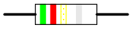
Example #1


A resistor colored Yellow-Violet-Orange-Gold would be 47 kΩ with a tolerance of +/- 5%.

Example #2


A resistor colored Green-Red-Gold-Silver would be 5.2 Ω with a tolerance of +/- 10%.

Example #3


A resistor colored White-Violet-Black would be 97 Ω with a tolerance of +/- 20%. When you see only three color bands on a resistor, you know that it is actually a 4-band code with a blank (20%) tolerance band.

Example #4


A resistor colored Orange-Orange-Black-Brown-Violet would be 3.3 kΩ with a tolerance of +/- 0.1%.

Example #5


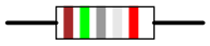
A resistor colored Brown-Green-Grey-Silver-Red would be 1.58 Ω with a tolerance of +/- 2%.

Example #6


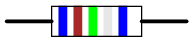
A resistor colored Blue-Brown-Green-Silver-Blue would be 6.15 Ω with a tolerance of +/- 0.25%.

Popular posts from this blog

how to make a lead acid accumulator battery charger

 lead acid accumulator charger circuit introduction: To charge a battery from an A.C source ,first you need a step down transformer, a rectifier and a voltage regulator  to maintain a constant voltage . then it can be used to charge a battery. if a D.C voltage source is available ,you only need a DC-DC voltage regulator , then give the volts to the battery DC VOLTAGE -→→DC VOLTAGE REGULATOR -→→BATTERY As seen in the DC voltage is given to the DC voltage regulator here we use LM317 which is a DC voltage regulator. The regulated DC out voltage is given to battery. There is also a trickle charge mode circuitry which will help to reduce the current when the battery is fully charged.   component of athe battery charger circuit LM317:   LM317 is voltage regulator invented by Robert C. Dobkin and Robert J. Widlar in 1970.the main function of this voltage regulator is to regulate the voltage and give the constant voltage without any noise disturbance; fo...

Flame Detectors Explained

 Flame sensor/ detectors: Flame detectors(sensors) detect the presence of flame.  just as every other sensor operate ; they detect a change in a physical phenomenon and then produce an output signal proportional to the change in the physical phenomenon being sensed or detected. The presence of fire which relates to flames is a physical condition to be watched against  and since this is an unwanted condition , there arise the need to constantly watch(detect) against it and eliminate it as quick as possible when detected . Flame detectors are devices that watch against flames (fire ) , it may also be called a fire detector.  A flame sensor detects a flame but what physical or measureable characteristics of a flame does it detects??. with this question in mind , we need to overview flames , identify the properties of a flame that can be detected /measured / sensed  and work on the best methodology to detect flames. OVERVIEW OF FLAMES A flame is a mixture of reac...

Diy project- inverter using 555timer

Today we are going to make a inverter using a 555timer.like I said earlier on principle of operation of an inverter (my previous post) we need an oscillating circuit and we are going to use an astable multivibrator (A astable multivibrator is an oscillating circuit that produce rectangular wave without the aid of an external triggering) such as a 555timer     Here below is the electronic components needed for this circuitry 1.555timer 2.BC547 npn transistor 3.15k resistor (4) 4.100k resistor 5.2N6292 transistor  6.12v battery 7.12-0-12 transformer 8.a breadboard or veroboard  or you can create a PCB (any of your choice) and a heat sink for the 2N6292 transistor. OK here is the circuit diagram Then you start the connection that all for now. Www.mydronelab.blogspot.com